|
|
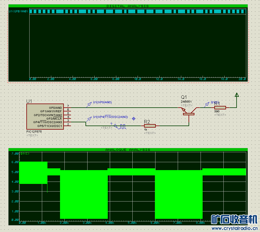
here is what I put together today.

and here is the code:- #include <htc.h> //we use picc
- #include <string.h> //we use strcpy
- #include "gpio.h"
- #include "config.h" //configuration words
- #include "delay.h" //software delays
- //hardware configuration
- #define RF_PORT GPIO
- #define RF_DDR TRISIO
- #define RF (1<<4) //rf out on gpio4 - do not change
- #define AF_PORT GPIO
- #define AF_DDR TRISIO
- #define AF (1<<0) //af out on gpio0
- #define BEEP_COUNT 100 //number of beeps
- #define DLY_GAP 100 //gap, in ms
- #define DLY_BEEP 1 //beep, in ms
- //end hardware configuration
- unsigned char cwRAM[17]; //cw send buffer
- void beep(unsigned char n) {
- while (n--) {
- IO_FLP(AF_PORT, AF); //flip af
- delay_ms(DLY_BEEP);
- };
- }
- #define gap() delay_ms(DLY_GAP)
- //send a dot = beep + gap;
- //#define dot() {beep(BEEP_COUNT); gap();}
- void dot(void) {
- beep(BEEP_COUNT);
- gap();
- }
- //send a dash = 3 beeps + gap
- //#define dash() {beep(BEEP_COUNT); beep(BEEP_COUNT); beep(BEEP_COUNT); gap();}
- void dash(void) {
- beep(BEEP_COUNT);
- beep(BEEP_COUNT);
- beep(BEEP_COUNT);
- gap();
- }
- //initialize the pins
- void cw_init(void) {
- //gp4 as output
- IO_OUT(RF_DDR, RF); //rf pin as output
-
- IO_OUT(AF_DDR, AF); //af as output
- }
- //send a letter
- //internaltional morse code
- void cw_send(unsigned char dat) {
- dat = (dat >= 97)? (dat - 32):dat;
- switch (dat) {
- //letters
- case 'A': dot(); dash(); break;
- case 'B': dash(); dot(); dot(); dot(); break;
- case 'C': dash(); dot(); dash(); dot(); break;
- case 'D': dash(); dot(); dot(); break;
- case 'E': dot(); break;
- case 'F': dot(); dot(); dash(); dot(); break;
- case 'G': dash(); dash(); dot(); break;
- case 'H': dot(); dot(); dot(); dot(); break;
- case 'I': dot(); dot(); break;
- case 'J': dot(); dash(); dash(); dash(); break;
- case 'K': dash(); dot(); dash(); break;
- case 'L': dot(); dash(); dot(); dot(); break;
- case 'M': dash(); dash(); break;
- case 'N': dash(); dot(); break;
- case 'O': dash(); dash(); dash(); break;
- case 'P': dot(); dash(); dash(); dot(); break;
- case 'Q': dash(); dash(); dot(); dash(); break;
- case 'R': dot(); dash(); dot(); break;
- case 'S': dot(); dot(); dot(); break;
- case 'T': dash(); break;
- case 'U': dot(); dot(); dash(); break;
- case 'V': dot(); dot(); dot(); dash(); break;
- case 'W': dot(); dash(); dash(); break;
- case 'X': dash(); dot(); dot(); dash(); break;
- case 'Y': dash(); dot(); dash(); dash(); break;
- case 'Z': dash(); dash(); dot(); dot(); break;
- //digits
- case '1': dot(); dash(); dash(); dash(); dash(); break;
- case '2': dot(); dot(); dash(); dash(); dash(); break;
- case '3': dot(); dot(); dot(); dash(); dash(); break;
- case '4': dot(); dot(); dot(); dot(); dash(); break;
- case '5': dot(); dot(); dot(); dot(); dot(); break;
- case '6': dash(); dot(); dot(); dot(); dot(); break;
- case '7': dash(); dash(); dot(); dot(); dot(); break;
- case '8': dash(); dash(); dash(); dot(); dot(); break;
- case '9': dash(); dash(); dash(); dash(); dot(); break;
- case '0': dash(); dash(); dash(); dash(); dash(); break;
- default: break; //do nothing
- }
- }
- //send a string
- void cw_str(unsigned char * str) {
- while (*str) //if str hasn't ended
- cw_send(*str++); //send the current string
- }
- void mcu_init(void) { //initialize the mcu
- ANSEL = 0x00; //porta are digital io
- //ANSELH = 0x00; //all portB is digital io
- CMCON = 0x07; //analog comparators off
- //IRCF2=1, IRCF1=1, IRCF0=0; //running at 4Mhz
- }
- int main(void) {
-
- mcu_init(); //initialize the mcu
- cw_init(); //reset cw
- while (1) {
- //IO_FLP(RF_PORT, RF);
- //cw_send('A'); cw_send('B'); cw_send('C');
- strcpy(cwRAM, "Hello, world!"), cw_str(cwRAM); //send the string
- }
- }
it is a morse code transmitter working on 1Mhz.
the heart of the transmitter is a mcu (in this case, a pic12f675, 8dip). I used the internal 4Mhz rc oscillator. the oscillator is configured so that on GP4 it outputs a 1Mhz RF signal.
the audio signal is generated on GP0 - in this case, it is international morse code for "Hello, world!".
The AF signal is applied to Q1's emitter, to modulate the RF signal applied to Q1's base. the antenna is a short straight wire (4-in in length) on Q1's collector.
when I put my radio to the little transmitter, I could hear the morse code being transmitted.
This can act like a handy 1Mhz signal generator, usefully when you try to get your radio to work.
note to all: it is most likely illegal where you live to operate without a license in the AM band. but this particular transmitter is very low power - the signal dropped out ~5 meters away from the transmitter.
enjoy.
ps: the code is very portable so it should be quite easy to port it to any mcu (either internal oscillator or crystal).
|
评分
-
1
查看全部评分
-
|